Introduction
The increasing need of occupation of alluvial soils to new constructions has allowed the challenge of creating new suitable solutions of soil improvement that optimize the work execution time and the economic questions. In the described context, it is presented in this paper the application of CSM technology for the improvement of the foundation soil in the construction of an industrial building in Fréjus, France.
The building, with an approximately rectangular geometry in plan, has an implantation area of about 3800 m². In the following figure is presented the location of the work.
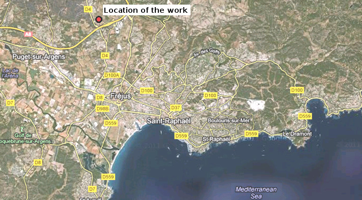
Figure 1 – Location of the work
The new industrial building presents only one high floor (Figure 2) and the respective surrounding is characterized by the absence of adjacent constructions.

Figure 2 – Representation of the final aspect of the new industrial building
The main concern during the design of the presented solution was the minimization of the total and differential settlements of the building structure.
According to the geotechnical conditions of the ground, it was necessary to transmit the efforts to the substrate with appropriate characteristics (marl-sandstone substrate), detected at variable depths between 3 m and 7 m. The performed solution to the efforts transmission consisted, generally, in soil-cement panels executed by the CSM technology. Above the CSM panels was executed a load transfer layer, 0.60 m thick, made of granular material, upon which was placed the concrete bottom slab of the building.
The CSM technology constitutes an interesting alternative to the traditional solutions, with some technical, economic and environmental advantages and it has been successfully applied in other cases of ground improvement (Ameratunga et al., 2009).
Main Constraints
Geological and Geotechnical conditions
The design of the presented solution was based in a geotechnical study of the ground site, including the execution of Cone Penetration Tests (CPT) and laboratory tests. The analysis of the obtained results allowed the identification of a superficial gravelly fill layer (Geotechnical Zone 1 – ZG1) detected to a maximum depth of 1 m, over colluvial soils (Geotechnical Zone 2 – ZG2) with high compressibility and low strength and a marl-sandstone substrate (Geotechnical Zone 3 – ZG3) detected at variable depths between 3 m and 7 m (Figure 3).
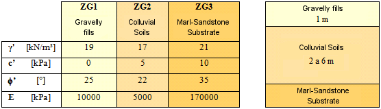
Figure 3 – Geotechnical zones and respective main geomechanical parameters
Execution time constraint
The contractor has imposed a maximum limit time of four weeks to the execution of the soil improvement. The proposed solution was conceived with the concern of achieving this objective.
Performed Solution
In the described context, the solution performed to assure the correct transmission of the efforts to the marl-sandstone substrate with appropriate characteristics of strength to the foundation, consisted of the execution of 118 CSM panels, with a rectangular cross-section with dimensions of 0.6 m x 2.4 m, disposed on a rectangular mesh, as illustrated in Figure 4.
The CSM panels were executed to variable depths between 3.5 m and 7.5 m to assure a minimum penetration of 0.5 m in the marl-sandstone substrate.
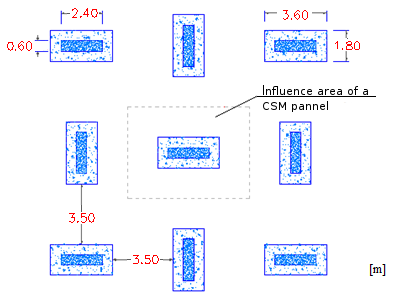
Figure 4 - Rectangular mesh of the CSM panels
To allow a more efficient loading transfer to the soil-cement panels it was performed the execution of an enlargement on the top of the panels, forming panel caps of larger dimensions than the panels in depth. The panel caps with dimensions in plan of 3.6 m x 1.8 m and 1 m height were executed through a small pre-excavation of 1.0 m depth with the geometry of the panel caps, subsequently filled by the overflow slurry resulting from the execution of the CSM panels.
The solution included also a load transfer layer, 0.60 m thick, made of granular material, upon which was placed the concrete bottom slab of the building. The following figure presents a view of some CSM panel caps.

Figure 5 - View of some panel caps
In figures 6 and 7 are presented, respectively, a cross-section and a plan view of the performed solution.
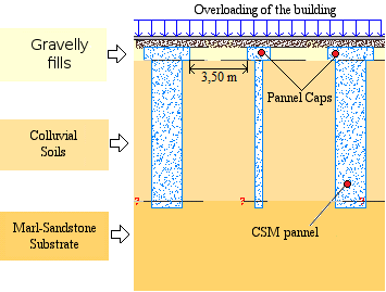
Figure 6 – Cross-section of the performed solution
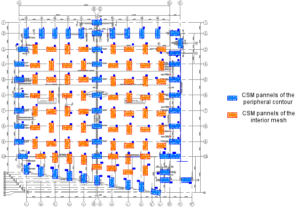
Figure 7 - Plan view of CSM panels distribution
With the application of this solution it was possible the execution of the soil improvement in the maximum limit time of four weeks, with an average daily execution rhythm of 6 CSM panels.
The CSM technology consists in the mechanical mixture of the in-situ soil with cement slurry to obtain soil-cement panels with improved resistance and deformability characteristics to allow its application, for example, in the execution of retaining walls, cutoff walls or foundation soil improvements (Gerressen et al., 2009).
The equipment consists of a hydromill with two sets of cutting wheels that rotate about a horizontal axis (Figures 8 and 9).

Figure 8 - Equipment to the application of CSM technology

Figure 9 – Execution of a CSM panel
In this case study, the use of the overflow slurry to fill the panel caps avoided the removal of excess cementitious material from the execution process.
The CSM equipment presents the versatility to allow the execution in all types of soils with the advantages of using the existing soil as a construction material, the minimization of the generation of spoil, the possibility of knowing the exact geometry of the panel in depth, the reduced vibrations during construction, among others.
Analysis Model
In an initial phase, the initial estimate of the CSM panels mesh was based on the limitation of the compressive strength on the CSM panels to a maximum value of 1,5 MPa, to service loads, admitting that the total load is transmitted to the panels.
Based on the initial defined mesh, the analysis of the solution in terms of long-term settlements was carried out using the finite element program PLAXIS®.
To the modelation of the existing ground conditions, the Mohr-Coulomb model was used, considering the geomechanical parameters indicated in section 2.1. To the modelation of the load transfer granular layer it was also used the Mohr-Coulomb model, with an elasticity modulus of 20 MPa and this parameter was afterwards submitted to validate in-situ tests.
The concrete slab of the building was simulated with a linear elastic model, considering an appropriated elasticity modulus to take into account fluency effects.
In Figure 10 are presented the simplified geometry, the finite element mesh and the boundary conditions of the numerical model.
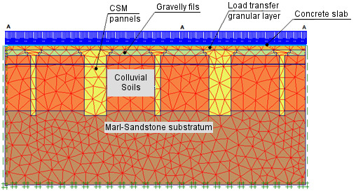
Figure 10 - Simplified geometry, finite elements mesh and boundary conditions of the numerical model
For the evaluation of the effects of the parameters variations, were carried out sensitivity analyses.
The results of the numerical analyses were evaluated in terms of angular distortions (β) that represents the measure of differential movement between two adjacent points separated by the distance. The angular distortion was in every studied cases lower than 1/800, with acceptable values of total and differential settlements. The maximum value of the long-term settlement obtained during analysis was 11 mm, which is within the settlement criterion.
In the following figure is presented the deformed mesh obtained in one of the numerical analysis.

Figure 11 - Deformed mesh obtained in one of the numerical analysis
Quality Control
Due to the particularities associated to the CSM execution process and, especially, due to the use of existing soil as a construction material, the quality control becomes essential to obtain the required characteristics and reproducibility on the panels executed.
The control was carried out, in an initial phase, during the execution of CSM panels by the rig operator that have the possibility to control and adjust the execution parameters in real time (Bringiotti et al., 2009).
In the following figure is presented the monitor of the rig operator to control the execution parameters.

Figure 12 - Rig operator’s monitor to control the execution parameters
The quality control is also carried out through the execution of unconfined compressive strength tests on samples from the CSM panels, to adjust the execution parameters and obtain the required characteristics of the soil-cement panels. In Table 1 are summarized the values of the compressive strength obtained in the two series of tests carried out on samples of the CSM panels.
| Series I | Series II | |
|---|---|---|
| Unconfined compressive strength (MPa) | 7.0 | 6.5 |
The design value of the compressive strength of the soil-cement panels was 1,5 MPa, with a safety factor of 2 and, because of that, the minimum value defined to the compressive strength of the samples collected for laboratory tests was 3 MPa. The results of the tests carried out after 7 days, presented in Table 1, evidenced that the compressive strength is highly superior to the required values. Because of that, the validation of the results was done without the tests after 14 and 28 days.
Conclusions
The Cutter Soil Mixing technology allows the use of the in-situ soil as a construction material and constitutes an alternative to the traditional solutions, with some technical, economic and environmental advantages. The panel caps executed at the top of the CSM panels ensured a more efficient transference of loads and with the use of the overflow slurry to fill the panel caps, the removal of excess cementitious material from the execution process wasn’t necessary.
It should be pointed out the excellent performance of this innovative solution to the improvement of the foundation soil in the presented case, finished in the required execution time.

Figure 13 – Views of the building after construction
References
Ameratunga, J., Brown, D., Ramachadran, R. and Denny, R. (2009). Ground improvement for a large above ground storage tank using cutter soil mixing columns. Proceedings of the 17th ICSMGE, pages 2280-2283.
Bringiotti, M., Dossi, M. and Nicastro, D. (2009). Miscelazione profonda dei terreni: metodi classici e tecnologie innovative – CSM by BAUER. Geofluid 2009.
Gerressen, F. W., Schopf, M. and Stotzer, E (2009). CSM – Cutter Soil Mixing – Wordwide experiences of a young soil mixing method. Proceedings of International Symposium on Deep Mixing & Admixture Stabilization, Okinawa, Japan.