Introduction
This paper is intended to present the case of the retaining structure for the excavation of "Parking Saint Nicolas", an underground parking lot in Cannes, France. For the construction of this underground parking, with a capacity for 420 cars, developed in four underground floors, was carried out an excavation to a maximum depth of 14 m. The excavation plan presents a rectangular geometry with dimensions of about 48 m x 55 m and is bounded by existing buildings and streets (Figure 1).
To the excavation of the underground parking was performed a retaining structure formed by soil-cement panels executed through the Cutter Soil Mixing (CSM) technology, with a rectangular cross-section and a geometry similar to the panels of diaphragm walls. The retaining wall was horizontally supported by two levels of reinforced concrete slab bands, executed along the perimeter of the work, creating a rigid support system of the four elevations. Temporary foundation micropiles were executed to, together with the retaining structure, allow the vertical support of the slab bands.

Figure 1 – Location of the work
During the conception of the solution and the execution of the work, one of the main concerns was assuring the minimization of the impact in the surrounding area.
In Figure 2 are represented two views of the exterior of the underground parking.
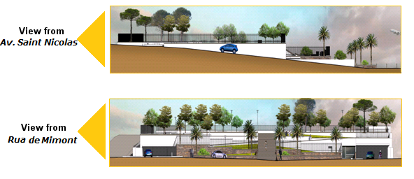
Figure 2 – Representation of two views of the exterior of the underground parking
CSM was developed from Deep Soil Mixing (DSM) technology and is based on the mixture of the in-situ soil with cement-slurry to create continuous walls formed by soil-cement panels of improved characteristics of strength and deformability, executed by a hydromill.
The CSM panels are produced by the mechanical action of the cutting wheels (Figure 3), rotating around a horizontal axis, by desegregating the soil and mixing it with the cement slurry added simultaneously. (Fiorotto et al., 2005).

Figure 3 – Detail of the cutting wheels (on the left) and general aspect of the hidromill (on the right)
Main Constraints
Geological and Geotechnical conditions
The evaluation of the ground conditions was based, in an initial phase, on the preliminary geotechnical study and in a second phase, in a second geotechnical study carried out to complement the first one.
The preliminary geotechnical study included the execution of three drill boring tests, three Ménard Pressiometer Tests (PMT) and a pumping test as well as the installation of five piezometers and the execution of laboratory tests. The second geotechnical study, carried out to complement the information obtained through the first study, included the execution of six PMT tests, the installation of three piezometers to measurements of the water table and the execution of laboratory tests.
The results of the in-situ tests together with the laboratory analysis allowed the identification of a heterogeneous geological context of the ground in the work site. The local soil is composed of a sandy clay layer detected from the surface to variable depths between 5 and 10 meters, overlying the substratum of marls. Table 1 presents the main geotechnical parameters, obtained by the interpretation of the in-situ and laboratory tests.
To the evaluation of the permeability, a hydrological study was carried out, which led to the values of the permeability coefficients (kh – horizontal permeability coefficient; kv – vertical permeability coefficient) also presented in Table 1. The hydrological study also enabled to define the minimum length of the panels below the bottom of the excavation to obtain the minimization of the water inflow to the interior of the excavation. With this aim, was defined to the CSM panels a minimum penetration length of 4 m below the bottom of the excavation, into the marl substrate. The water table was detected approximately 5 m below the surface.
| Sandy Clays (upstream) |
Sandy Clays (downstream) |
Altered Marls | Hard Marls | |
|---|---|---|---|---|
| γ [kN/m3] | 19 | 19 | 19 | 22 |
| c′ [kPa] | 10 | 10 | 25 | 70 |
| ϕ′ [°] | 25 | 25 | 25 | 30 |
| Es [MPa] | 15 | 6 | 6 | 225 |
| kh [m/s] | 1x10⁻⁴ | 1x10⁻⁴ | 2.5x10⁻⁶ | 2.5x10⁻⁶ |
| kv [m/s] | 5x10⁻⁵ | 5x10⁻⁵ | 2.5x10⁻⁶ | 2.5x10⁻⁶ |
Neighbouring constraints
The work is located in an urban zone and it is bounded by neighbouring streets and buildings. To ensure the minimization of the impact in the surrounding area, a rigorous accompaniment of the movements of the retaining structure throughout the different phases of the work is essential.
The work site is bounded to the north by an existing building with four floors high and an underground floor, to the south by streets (Boulevard d’Alsace / Rue de Mimont) to the west by an avenue (Avenue Saint Nicolas) and to the east by an existing building with four floors high and three underground floors.
CSM Retaining Wall
The retaining wall performed to the excavation of the underground parking lot consists of a continuous CSM retaining wall, reinforced by vertical steel piles (IPE piles) along the panels in depth.
Each panel of the retaining wall was reinforced by two vertical steel piles (IPE 450), installed at 1.1 m intervals. The CSM mixing tool used, allows the execution of soil-cement panels with a rectangular cross-section, with dimensions of 2.4 m x 0.6 m. The continuous wall was obtained by overlapping primary and secondary panels, with a minimum overlap length of 0.2 m to assure an efficient connection between panels in depth (Figure 4).
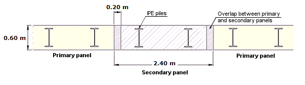
Figure 4 – Representation of the overlapping of primary and secondary panels of the CSM retaining wall
At the top of the retaining wall a concrete beam was executed to connect all steel soldier piles.
The horizontal support of the CSM wall was performed by two levels of concrete slab bands, creating a rigid support system of the four elevations that were afterwards incorporated in the structure of the building. The two slab bands were executed at the “0” and “-2” floors. The horizontal support in small slab holes was guaranteed by small steel struts. The temporary support of the slab bands was performed by foundation micropiles (N80 ф177,8 x 10 mm – API5A) with a Gewi bar (ф50 mm) in the interior.
The solution included a 0.2 m thick concrete wall, executed against the CSM wall during the progress of the excavation.
In the case of this excavation with the presented dimensions, an alternative solution using steel pipe struts would require the use of large diameter and big length steel struts and, due to the surrounding conditions, the execution of ground anchors wouldn’t be viable. The use of slab bands to a horizontal support of the CSM retaining structure was considered technical and economical advantageous, presenting as the main advantage the incorporation of elements used in the final structure at the preliminary stage of the work.
Figure 5 presents a partial view of the work with the slab bands and the temporary foundation micropiles and a cross-section of the retaining wall structure.
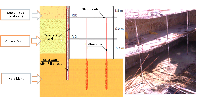
Figure 5 – Partial view of the work (on the left) and cross-section of the retaining wall (on the right)
The slab bands are connected to the CSM wall through horizontal rolled steel profiles (HEA profiles) incorporated into the slabs and directly connected to the vertical steel piles of the CSM wall.
Figure 6 presents a plan view of the general configuration of the retaining wall structure. The peripheral CSM wall was composed of a total of 95 CSM panels. For the temporary support of the slab bands were executed 28 foundation micropiles.
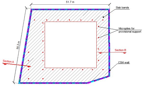
Figure 6 – Plan view of the general configuration of the retaining wall structure
Analysis Model of the Retaining Wall
In the analysis of the retaining wall were defined four cross-sections to represent the four elevations of the retaining wall.
The performance of the retaining wall was evaluated using the finite element program PLAXIS®. Through the referred program, all the phases of the execution process were modelled to obtain numerical simulations as close as possible to the real situations. The ground was modelled using the Hardening Soil model with the geomechanical parameters presented in section 2.1. The analysis included the determination of the maximum values of the efforts and displacements of the retaining wall.
In figures 7 and 8 are presented two sections of the model studied: Section A, representing a cross-section of the west alignment of the retaining wall and Section B representing a cross-section of the east alignment.
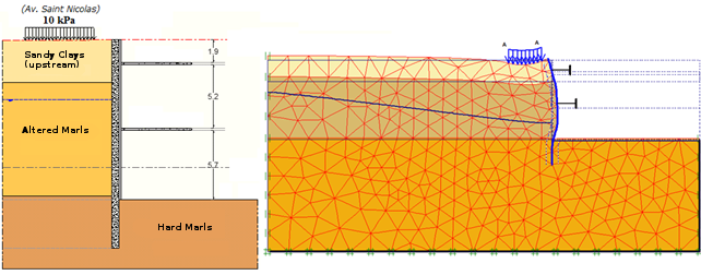
Figure 7 – Section A: cross-section (on the left) and analysis model representing the deformation at the maximum excavation depth (on the right)
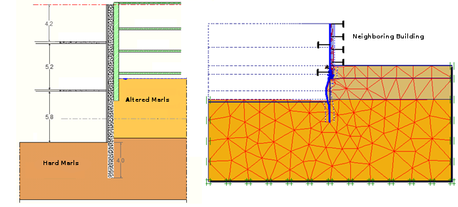
Figure 8 – Section B: cross-section (on the left) and analysis model representing the deformation at the maximum excavation depth (on the right)
The simulation of the execution process started with the CSM wall construction. In another phase was simulated the first level of excavation, to a maximum depth of 0.5 m below the first level of the slab bands and the third phase consisted in the simulation of the execution of the first level of slab bands. In a subsequent phase was modelled the excavation to a maximum depth of 0.5 m below the second level of the slab bands. The fifth phase consisted in the simulation of the execution of the second level of slab bands and, in a final phase was modelled the excavation to the maximum depth.
Table 2 presents the maximum horizontal displacements of the retaining structure obtained in the numerical analyses of sections A and B.
| Displacements horizontal maximum (mm) | ||
|---|---|---|
| Section A | Section B | |
| Top of the retaining wall | -8.0 | 0.2 |
| Along the height of the retaining wall | 15.0 | 5.0 |
The results obtained in the numerical analyses of all studied sections are in the range of values considered acceptable to the characteristics of this excavation.
Regarding the results obtained to Section B it should be pointed out that the retaining wall is bounded in this alignment by a building with three underground floors. Until the excavation reaches the corresponding depth of the bottom slab of the neighbouring building, practically no efforts and displacements were introduced in the retaining structure. For deep excavation phases were obtained horizontal displacements and efforts in the retaining wall with low values, due to the small depth of excavation below the foundations of the neighbouring building.
The design of the reinforcements to the slab bands to its correct performance during the temporary phase was based on the maximum efforts obtained in the numerical simulations.
Execution Process
The execution principle of the CSM technology consists in the desegregation and mixture of the existing soil with cement slurry, to obtain rectangular soil-cement panels with strength and deformability values defined in the design phase (Arnold et al. 2011).
The execution process started with the execution of a CSM test panel to obtain samples for laboratory tests and to allow the calibration of the execution parameters. The equipment used to realize the CSM panels allows the rig operator to control in real-time the execution parameters (Bringiotti et al., 2009).
After the initial phase of the equipment calibration, the panels of the retaining wall were executed. Immediately after the execution of each panel and before the hardening of soil-cement, were installed two vertical steel piles (IPE 450) in each soil-cement panel. In this stage were also installed the inclinometers behind the retaining wall to the control of the horizontal movements. The succeeding phase consisted in the execution of the foundation micropiles to the temporary support of the slab bands (Figure 9).

Figure 9 – Foundation micropiles to the temporary support of the slab bands
The solution included the execution of a concrete beam in the top of the retaining wall, connecting all vertical steel piles.
The first level of excavation was carried out to a maximum depth of 0.5 m below to the first level of slab bands. After the execution of the first level of excavation, horizontal rolled steel profiles (HEA profiles) with a length of about 0.50 m were connected to the vertical steel piles of the retaining wall to allow the connection between the retaining wall and the concrete slab bands.
In this phase, the first level of slab bands was executed at the level of stage “0”. To monitor the movements, surveying targets were installed in the slab bands at this stage.
The subsequent phase consisted in the excavation to a maximum depth of 0.5 m below the second level of slab bands. Figure 10 presents two views of the work during this phase.

Figure 11 – View of the work during the execution of the first level of excavation
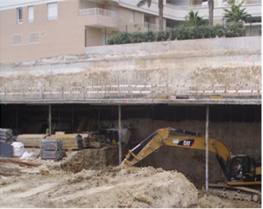
Figure 12 – View of the work during the execution of the second level of excavation
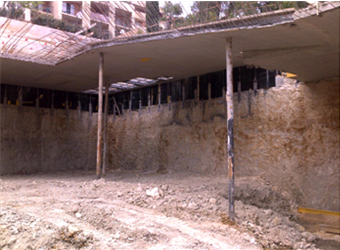
Figure 13 – View of the work during the second level of excavation
After the execution of the second level of the slab bands at the level of stage “-2”, was carried out the excavation to the maximum depth. The CSM panels were executed to a depth that allowed the minimization of the water inflow to the interior of the excavation, to make more efficient the excavation process.
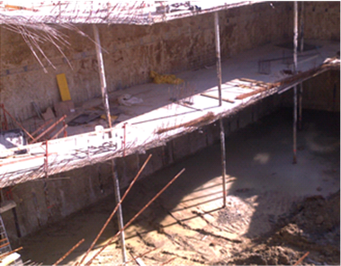
Figure 14 – View of the work after the execution of the second level of slab bands
Once the maximum depth of excavation is reached, the bottom concrete slab and the internal structure of the underground parking were executed and the temporary foundation micropiles were deactivated. Figure 15 presents the general aspect in the final phase of the work.

Figure 15 – General aspect in the final phase of the work
Quality Control and Monitoring Plan
The quality control of the work was carried out at different levels. In an initial phase, during the execution of the CSM panels, was performed the control, in real time, of the execution parameters by the rig operator. A second level of control was carried out by laboratory tests (unconfined compressive strength tests) on samples from a CSM test panel and from the panels of the CSM retaining wall. During the excavation, the control of the work was performed by the implementation of a monitoring plan, including the installation of surveying targets and inclinometers. The temporary foundation elements were also subject to control through the execution of Load Tests.
The results obtained in the unconfined compressive strength tests on samples from the panels of the CSM retaining wall are presented in Table 3.
| Tests Series | Number of tested samples |
Unconfined compressive strength (MPa) | |||
|---|---|---|---|---|---|
| 3 days | 7 days | 14 days | 28 days | ||
| Series I | 6 | 4.4 | 6.5 | 8.4 | - |
| Series II | 6 | - | 2.5 | 4.5 | 8.0 |
| Series III | 4 | - | 2.5 | 4.5 | - |
| Series IV | 4 | - | 2.5 | 6.0 | - |
The compressive strength of the samples tested after 14 days are higher than the required design strength (4 MPa) in every performed series of tests.
Figure 16 presents the location of the 19 surveying targets and the 3 inclinometers installed according to the monitoring plan of the work. The surveying targets were installed at the first level of the concrete slab bands. The installation of inclinometers and the surveying targets allowed the measurement of lateral movement and deformation of the retaining wall as the excavation progressed. The inclinometer and the surveying targets were read manually during the excavation.
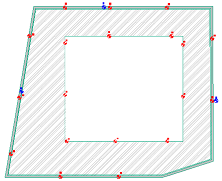
Figure 16 – Surveying targets and inclinometers installed according to the monitoring plan of the work
The results obtained in the monitoring of the work presented lower values than the alert limits defined. As it would be expected, in the parallel direction of the retaining wall practically no displacements of the retaining wall were observed and in the perpendicular direction, were observed the main displacements of the retaining wall.
It should be pointed out the importance of the control and monitoring of the work as an essential tool to the reduction of the risk to the work site and to the surrounding constructions, especially in urban excavations, allowing in advance the prevention of problems in the execution process.
Conclusions
The paper has pointed out the good performance of the application of the Cutter Soil Mixing technology to the execution of the retaining wall to allow the excavation of "Parking Saint Nicolas”, an underground parking lot located in Cannes, France. The main objectives of the work were achieved. The CSM wall allowed the execution of a vertical excavation with a maximum depth of 14 m and the reduction of the water inflow to the interior of the excavation.
The horizontal support of the retaining structure using concrete slab bands was one of the most significant advantages of the presented solution, allowing the integration of elements of the final structure at a preliminary stage of the work to avoid the temporary elements of horizontal support as grouting anchors or steel struts. The use of slab bands as horizontal supports of the retaining structure has some advantages when compared with ground anchors because of the non-occupation of the neighbouring ground and the elimination of problems related to its execution below the water table (problems of internal erosion). The presented work constitutes a good example of a technical, economical and environmentally interesting solution.
References
Arnold, M., Beckhaus, K. and Wiedenmann, U. (2011). Cut-off wall construction using Cutter Soil Mixing: a case study. Geotechnik, volume 34: pages 11-21.
Bringiotti, M., Dossi, M. and Nicastro, D. (2009). Miscelazione profonda dei terreni: metodi classici e tecnologie innovative – CSM by BAUER. Geofluid 2009.
Fiorotto, R., Schöpf, M. and Stötzer, E. (2005). Cutter Soil Mixing (CSM) An innovation in Soil mixing for creating Cut-off and Retaining walls. In:16 ICSMGE: International Conference on soil mechanics and geotechnical engineering, Osaka-Japan.
Matos Fernandes, M., Peixoto, A., Pinto, A., Pita, X., Topa Gomes, A. e Gomes Pedro, A. (2010). Cutter Soil Mixing aplicada a escavações urbanas. COBRAMSEG 2010: Engenharia Geotécnica para o desenvolvimento, inovação e sustentabilidade. COBRAMSEG 2010 - Congresso Brasileiro de Mecânica dos Solos e Engenharia Geotécnica, 2010, Gramado, Brasil.